|
FT-102 Overshoot Fix by Mal - NC4L |
A Fix for the Previous Modification The previous modification had two very serious drawbacks:
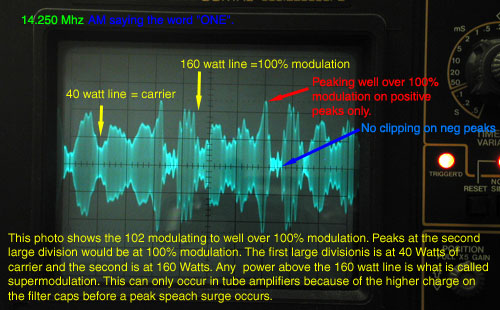
The Key Down Surge Problem The FT-102 has a serious surge or overshoot of power when first keyed in the AM mode. If you are driving a linear, the surge may cause damage to the amp's tubes (or transistors), or cause protection circuitry in the amp to shut it down. Further, even if your amp survives, it is likely to be overloaded for a brief period and the first few words of your transmission will be distorted and cause splatter due to flattopping. Actually, this will occur even if you use the 102 barefoot, although the splatter will be less noticable due to the lower power. But good amatuer practice is to avoid splatter no matter the power level. Let's look at the severity of the problem. When I look at the power surge on the scope I can see an enormous surge when the 102 is first keyed in the AM mode. I run my rig at 40 watts out on AM. If my carrier is set to 40 watts and I key down the surge extends to over 200 watts. The reason that surge exceeds my usual steady state key down power of 160 watts (when the mode switch is in the tune or CW positions) is that the 102 is a tube amp and the caps charge higher in any quiescent mode. That used to be called dynamic headroom in the old Hi-Fi terminology. It is also the reason that the 102 can easily exceed 100% modulation in AM on the positive peaks. That cannot occur with solid state driven exciter amps, as the ALC in these transceivers will stop any power increase beyond saturation, stone cold. I usually get all the 102s to run at 110% modulation after peaking the AM tank on the board and making sure that the voltage inputs to the two circuits on the chip are in the right relationship.
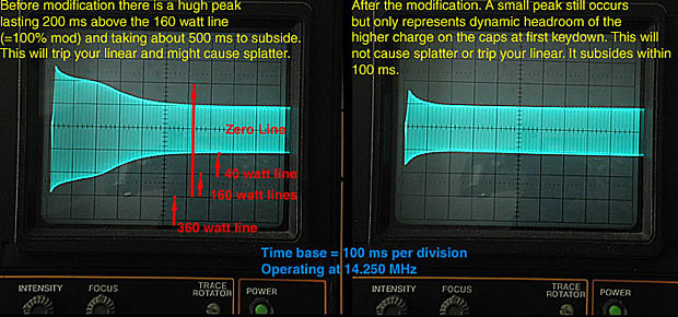
Figure 1 - Scope display of a properly tuned and operating FT-102 on AM. The key down surge starts at over 200 watts and stays at over 160 watts for 250 milliseconds (mS) and then gradually subsides over another half second. After the modifications described below, there is a minor peak (represents dynamic headroom of the amp) to about 60 watts and then back to normal carrier within 30 mS of keydown. This very small surge will not trip any linear amp protection circuits.
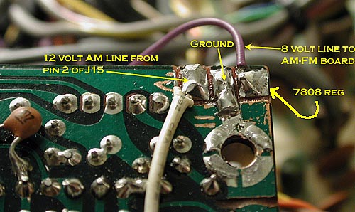
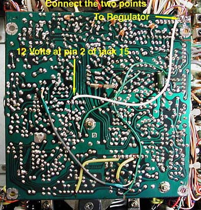
Figure 2 - Scope display of the power surge: before modification at left, after modification on right. The Modifications Starting from an unmodified radio and FM-AM Unit (PB-2347), cut the wire going to pin 1 of P60 (J01). Leave enough room (about 2 inches) to solder another lead to it and insulate the other cut end which carried the old 8 volt supply to pin 1, so it doesn't short out. Then go to the AF Board/Unit (PB-2344) and pick up a lead from pin 2 of J15/P38. This is noted to be a 12 Volt AM line. It is energized only when in the AM mode, and is on continuously in both receive and transmit. It is not on in FM or any other mode. This will be your new power source for the AM unit but it must first be converted to 8 volts. I recommend using a 7808L regulator (cost is well under a dollar) to bring the 12 volts to 8V. The photos below show where and how to install the 7808L on the AF Board/Unit (PB-2344). Connect this 8 volt line to the wire from pin 1 of P60 and it is done. This will give you constant 8 volts at pin 1 of plug 60, but only in the AM mode and will be activate in both receive and transmit. This power line will not be active on FM or any other mode so that AM cannot interfere with FM functions since it will not be switched on. The nice thing with this modification is that this modified radio and the unmodified boards are both forward and backward compatible.
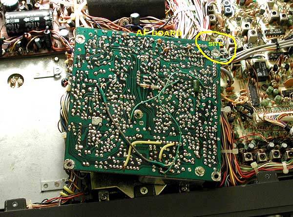
Figure 3 - The regulator (7808) will be placed in the upper right hand corner of the AF Board.
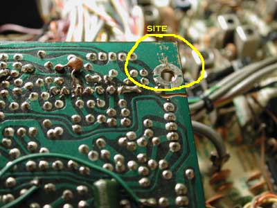
Figure 4 - There is a little unused real estate just above the mounting hole.
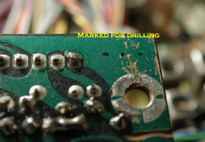
Figure 5 - Using the 7808 pins as a template (or calipers, ruler of some other measuring tool) mark the board and then drill the holes.
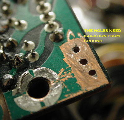
Figure 6 - Scrape off the conformal coating around the holes for about 1/16 inch. I used a Dremel battery operated drill and a dental bit but many other things will work out.
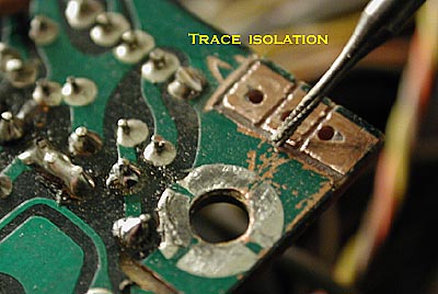
Figure 7 - Scrape away the copper between each hole to make a solder pad for each leg/terminal of the 7808.
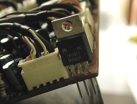
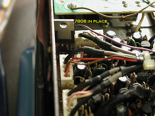
Figure 8 - Be sure to insert the 7808 as shown. Because the radio was rotated 180 degrees to get this photo, please make sure that the printing on the plastic part of the regulator faces away from the board. Polarity counts!
Figure 9 - Solder the connections shown and described in the text above and you are almost done.
Figure 10 - View of the back side of the completed AF Board (PB-2344).
Figure 11 - Reinstall the AF and AM/FM boards and test. Again note the orientation of the 7808 at the time of final installation in the photo. The plastic part with writing should face toward the PA board. Conclusion The FT-102 is a great rig for AM, FM, CW and SSB. The mods above will make it a much better performer on AM, especially when using it with a linear amplifier. If you are interested in more information and other modifications on the FT-102, please visit my Web page at www.members.aol.com/NC4LMAL. And if you run into trouble, contact me for assistance at NC4LMal@aol.com. High Resolution Images Since first performing this modification, I have perfected and and documented the steps with a series of high resolution photos. These photos are numbered and if followed in sequence show all the steps that are required to do the modification professionally.To the Photos |