|
An Improved Three Diode Negative Peak Limiter by Steve - WA1QIX |
|
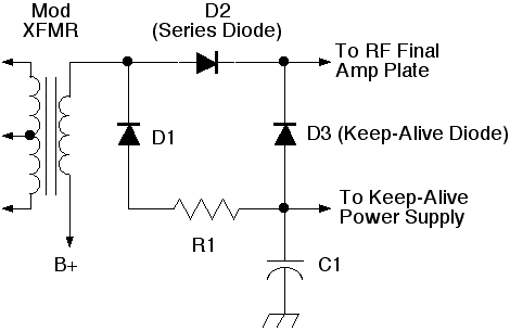
Background The three diode limter circuit below uses a keep-alive circuit instead of a tapped resistor, as in other negative peak limiter cicuits. This circuit provides a more constant load to the modulators and produces less distortion than other circuits. Circuit Details R1 = Plate Impedance of the RF Amplifier, power rating equals 1/20 of the modulator power. C1 = 20-40 uF. C1 is not needed if the keep-alive power supply has a similar cap on its output. Keep-alive power supply = 1/10 to 1/20 the B+ voltage, e.g. B+ = 1000 V, Keep-alive = 50 V. Current requirement is about 1/10 the current rating of the B+ supply. D1 and D3 voltage ratings should be at least four times the B+ Voltage for a good safety factor. D1 and D3 current ratings are about 1/10 the DC plate current of the RF final amplifier. D2 voltage ratings should be at least the B+ Voltage (preferably higher). D2 current rating should be three times the DC plate current of the RF final amplifier. Maximum negative modulation is controlled by the Keep-alive power supply voltage. The voltage level should be made variable with a variac or suitable sized rheostat.
|
