| Notes
on Putting a Hallicrafters HT-32 Transmitter Back on the Air by Ken - K6FC |
|
Last
spring I asked a good friend, W3JN, to look around at NEARFEST for an
HT-32 for me, as I was interested in resurrecting a rig that had been a
dream transmitter when I was in high school in the 50’s. At
the
time that rig cost about one-half the price of a new car and it was
something a poor teenager could only drool over at the local ham
store. John never saw one in New England, but he did find one
in
Maryland that was advertised as having low output, but was reasonably
priced and not too bad cosmetically. On a subsequent trip to
the
Washington, DC area I picked up the rig – although at 80+ pounds
“picking up” wasn’t quite the operative term!
After putting it on the bench, I slowly brought up the AC with a VARIAC. No smoke, certainly a good sign. As advertised, the power output was quite low. The tubes all tested at least in the acceptable range and the power supply voltages were close to nominal values. I downloaded an HT-32 manual from BAMA and followed the alignment instructions – still it was a QRP rig! At this point I really started to study the manual in earnest. What follows describes the fix for this problem and several modifications to improve performance and utility. The Low Output Problem Using a VTVM I found the output of the 8 MHz SSB/CW generator to be anemic. A measurement of the control grid bias voltage on the 6AU6 generator amplifier (V5) showed about –14 volts in the SSB mode and a range of –9 to –20 volts (RF level control) in CW. Now a 6AU6 is a sharp cutoff pentode and these values of control grid voltage just about assure the tube will not provide much amplification. A “tweaking” of the “factory adjust” 300K gain control (R161) enabled an RF level control range of about –8 to –18 volts: still a lot of negative bias. A review of the tube base voltage chart (figure 11 in the manual) indicated this voltage should be in the range of –2.8 to –10 volts. Using the resistance values shown in the schematic for the bias voltage divider network (R155 through R161), I calculated the expected bias and confirmed the higher range as measured at the grid! The only thought I had was the schematic was wrong – but then, so were the installed resistors! While I didn’t understand how both the schematic and component values could be wrong, I wanted the bias in a range where the tube provided amplification. The resistor that is labeled R160 was shown as 220K (unfortunately not noted in the parts list). I replaced this resistor with 22K (was this a schematic error?) and now could get the –2.8 to –10 volt bias values using the “factory adjust” control – R161. The good news now was the rig put out plenty of power on all bands. (Note: changing R160 necessitated removal of the 8 MHz subchassis assembly. Start this action with the removal of the front panel and proceed carefully.) VOX Issues In using VOX, the transmit relay would often not release following speech, leaving the rig in the transmit mode. The 12AT7 relay tube (V17) was not totally cutting off and the small amount of plate current was enough to keep relay RY1 engaged. This problem was resolved by increasing the bias voltage on the 12AT7 cathode. Replace R50, an 82K resistor, with a 56K resistor. There was also a short delay in the VOX relay pickup after the startup of speech. C85, a 0.22 uf capacitor from the relay tube control grid to ground was changed to 0.1 uf. This allows a faster attack time and the resulting change in relay hold time is made up with an adjustment of the delay potentiometer, R49. Low Voltage Filter Capacitors The low voltage power supply filter utilizes a capacitor input choke filter and produces 300 volts DC. The input cap (40 uf) and the output cap (60 uf) are enclosed in a single can. Amazingly the original dual electrolytic (C79) hadn’t lost much in the way of capacity over the years, however the dissipation factor for both caps was above 0.6 (max on my meter). While the unit might last another generation, the high “D” factor led to a decision for replacement. The dual cap was removed and replaced with a single 150 uf 450 volt cap connected on the output side of the filter choke, L25. A new 5 uf 450 volt cap, placed under the chassis, was used at the input to the choke. Reducing the input capacitor value reduces the reactive current in the power transformer secondary and thus reduces undesirable heating of the transformer. A measurement of the DC output voltage following these changes showed it remained at 300 and a decision to solid state the 5V4 rectifier (V19) was abandoned as unnecessary. AC Line Cord and Antenna Relay Power The HT-32 still had the original power cord and it was replaced with a three wire grounded power cord with the “hot” wire going to the fuse and then to the on-off switch. Now one doesn’t get a little “jolt” when touching the chassis! The instruction manual shows how RY1 contacts can be used to power an external antenna relay via external power. Contacts G, H, and I on RY1 were disconnected from the control outlet (pins 2,3,4) on the chassis rear panel. Contact I was connected to the on-off switched 115 VAC (at the fan socket) and contact H was attached to a new two-contact polarized Jones socket mounted on the rear panel. The socket neutral was connected to the neutral from the AC line cord. (Note: the Jones socket/plug is “my standard” for connecting an antenna relay and is installed in all my restored “Boat Anchors”.) On transmit 115 VAC power is now available directly through this socket. Push to Talk (PTT) I have a foot switch I use with my restored Viking II and I thought it would be useful with the HT-32. A line was run from the bottom of R51 (470 ohms) to pin 2 of the control outlet. When pin 2 is grounded (to pin 1) RY1 is activated just as it would be with VOX or manual operation. When using this feature it is best to disable the VOX through a reduction of the VOX gain (R42). The Bias Supply and Adjustment A previous owner had replaced the original selenium rectifier with silicon but had kept the two filter caps at 12 uf per the schematic. An additional 100 uf 250 volt capacitor was put on the output of the rectifier to make sure there was a lot of filtering! The instruction manual says to set the amplifier bias at –49 volts (R61). Unfortunately this tells nothing about the no-signal plate current of the 6146’s in the PA, as there is no plate current meter in this rig. The line from filter choke L26 to the amplifiers was temporarily broken and a 200 milliamp meter was wired in. In accordance with the tube specifications, the bias was set to indicate a plate current of 28 milliamps. The actual bias for this plate current was –53 volts. Miscellaneous Small knobs were affixed to the VOX and anti-trip gain potentiometers and the VOX delay potentiometer. It is now much easier to make minor adjustments to these controls. I had a limited number of IERC tube shields (they are supposed to reduce tube temperatures) and used them to replace the original bright aluminum shields. As can be seen in the second photo I didn’t have enough of them to go around! Although this transmitter is over 50 years old, quality components must have been used in its construction as those I checked almost universally remained within their original tolerance. I still can’t fathom how this situation arose, but the fix (once the deficiency was discovered) is certainly straightforward. I purposely didn’t go into any detail on the changes noted above as they are not complicated and easily accomplished. Only basic tools are needed. That said, there are lethal voltages to be found with the transmitter outside its cabinet and safety is the prime concern with old tube equipment. Always unplug the transmitter before making any circuit changes! Photos |
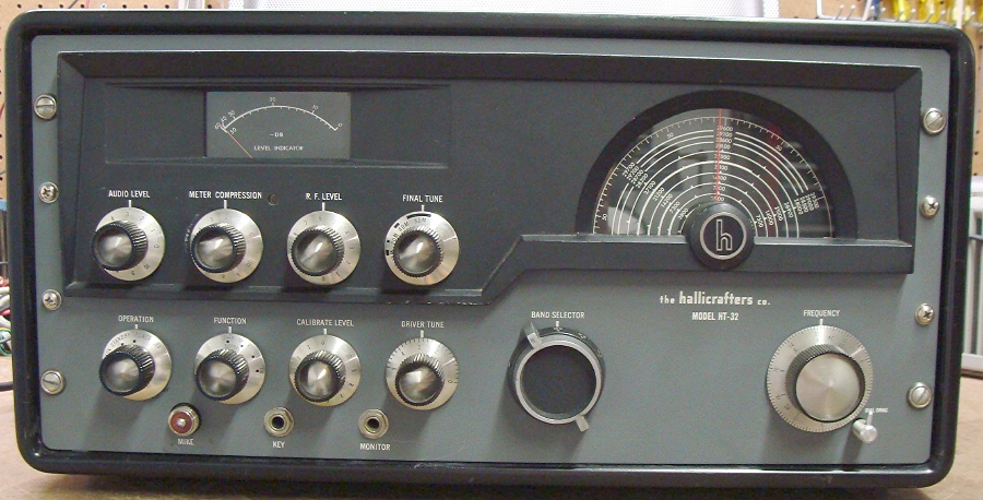
Front Panel
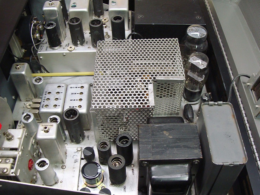
Inside
the Top Cover – New 150 uf filter cap bottom left
Added knobs appear around the filter cap
Added knobs appear around the filter cap
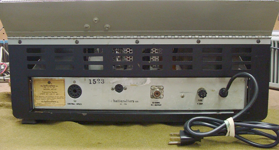
Rear Deck – note added Jones plug for antenna relay just above Hallicrafters name